Another arcade stick find from internet auction. This time the Saitek Titan Series Megamaster VII MX-541 for the Sega Mega Drive (Genesis). I think this was most commonly known just as Megamaster VII.
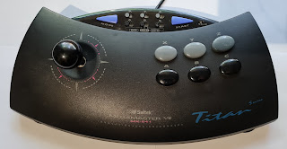 |
| Saitek Megamaster VII |
 |
Next to original Mega Drive model 1. Quite massive controller.
|
I got this one for cheap since the seller said that there was some problems with the Z-button not working correctly. I thought that should be fixable and this thing deserves to be fixed. Saitek made some quality controllers and this one is no exception. So lets start disassembling.
 |
Back of the controller. Chunky suction cups.
|
First thing I noticed was this strange door. What could be the purpose of this.
 |
Hidden compartment
|
Well there was absolutely nothing there. Looks like it might be battery holder for 2 AA batteries but I'm not aware they made wireless version of this stick. Maybe they were planning to.
 |
Empty
|
All the screws were visible except for one that was hiding under rubber cap.
 |
| Hidden screw |
 |
All the back plate screws removed
|
Gently lifting the back plate reveals the innards. The front and back are connected with wires. There is enough slack to get the halves separated.
 |
Back plate removed
|
First things I noticed were the metal plates on either side to give this thing some weight. Then there was the stick with proper micro switches. And rats nest of wires. Looks like there is no easy way to separate the two halves. Luckily there is enough slack to have decent room to work with. Here are some more detailed pictures of the innards.
 |
| Strain relief |
 |
| Joystick micro switches |
 |
Main PCB and turbo/auto fire auxiliary PCB
|
Have to say that while the mechanical construction is quite solid the soldering looks kind of bad. And those wires are really thin. I managed to snap couple of them while doing the repairs and without pictures I would have had really difficult time tracking where everything goes. Also strange mismatch of screws. The main PCB has 1 screw with collar and 2 without. The auxiliary PCB has 2 collared screws. Onward with disassembly.
 |
| Main PCB |
 |
Auxiliary PCB
|
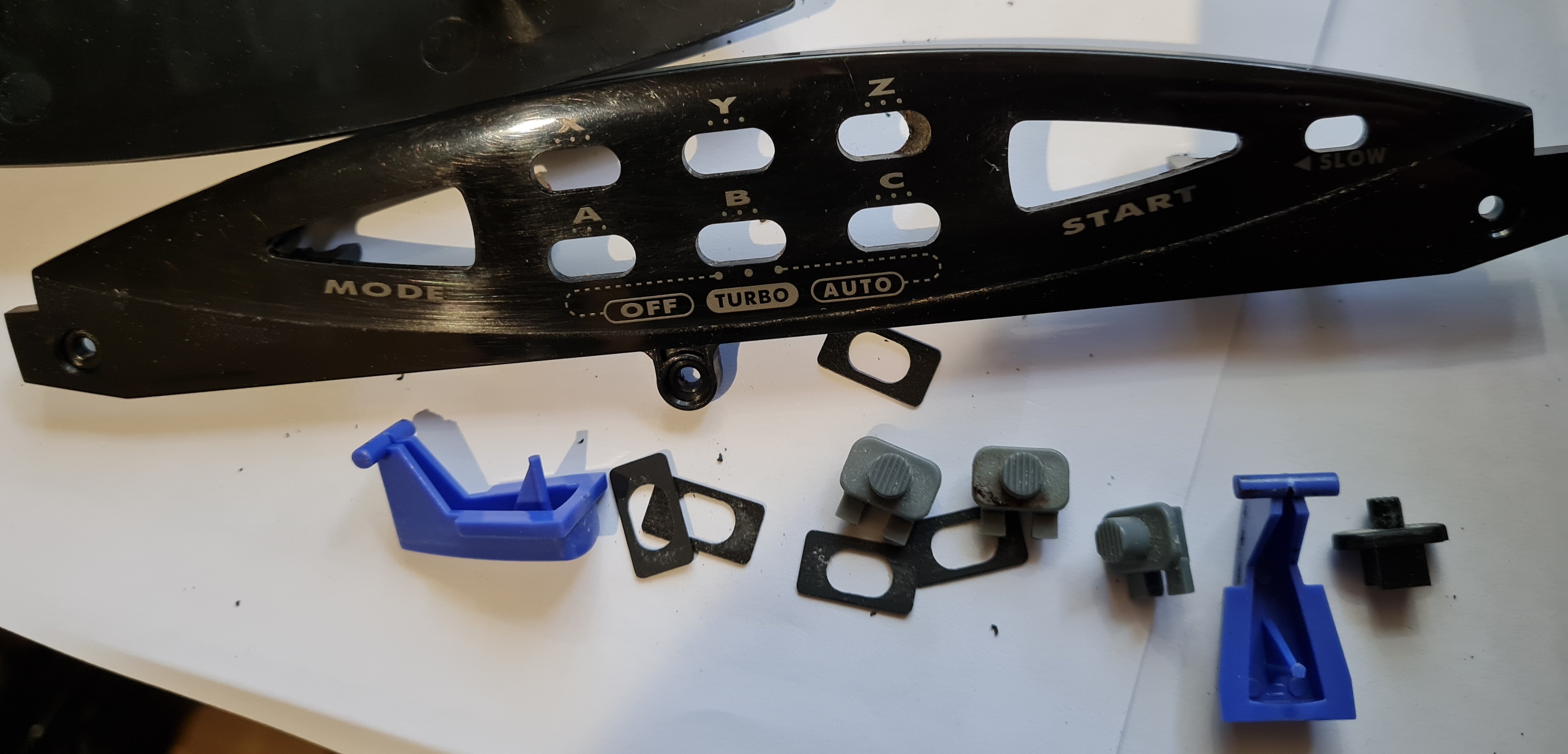
Once removing the screws both PCBs they can be lifted up. There is just enough slack in the wires to turn them around. The controller chip is interestingly a separate PCB with glob top IC. Maybe some generic controller everybody was using back then. I was happy to find that the buttons also have proper micro switches. The auxiliary board sliders are really fiddly. There are 2 rows of 3 position switches and mechanics are shifted upwards using plastic sliders. The feel of the assembly is awful and it is really difficult to put back together. There are also separate plastic collars around the sliders.
 |
Auxiliary board mechanics
|
 |
| All the fiddly plastic parts of the auxiliary board mechanics |
Lifting up the main PCB revealed also the buttons. They are held in the front plastic with clips. They are easy to remove with pair of tweezers. There are springs to give some extra resistance so they just don't sit on top of the micro switch levers.
 |
| Buttons |
 |
Buttons removed
|
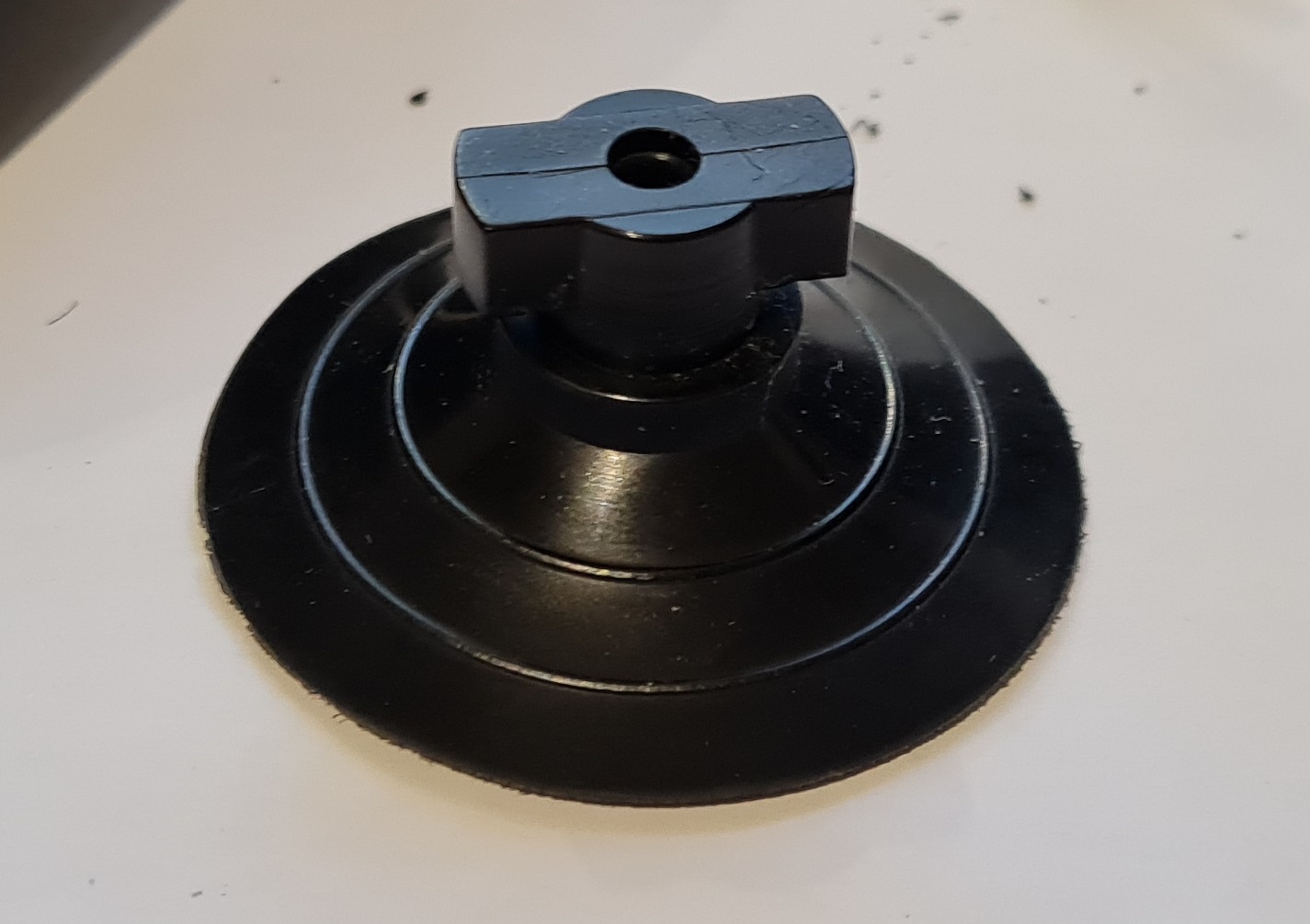
I wanted to clean this thing as thoroughly as possible so I checked if I could remove the suction cups for cleaning. The holders were strangely over engineered. There are 2 screws holding a cap on top of the suction cups. When the cap is removed you can see that you need to twist the suction cup 90 degrees while pushing it upwards to remove it. You could do this without removing the cap also. I have no idea why the cap was not just molded to the back plate plastics.
 |
| Suction cup holder removed |
 |
| Suction cup removed |
Finally I had all the loose parts removed and gave those good clean with soap and water. I also wiped down the front and back plastics as best as I could. So now was time to do troubleshooting to see what was wrong with this stick. I connected the stick to a PC with an adapter and indeed the Z-button was not working. But also the up direction was not working. Next I checked the continuity of all the micro switches and concluded that those were working fine. So the problem had to be in the wires. And checking the wiring diagram of Mega Drive controller port I noticed that in 6-button mode the Z and up are shared in pin 1. So it might be that just one wire is broken somewhere. So next thing was to check continuity from the glob top IC all the way to the connector. I used a paper clip in the connector to make probing easier.
 |
| Paperclip to the rescue |
 |
| Checking continuity |
After fiddling around a bit I managed to figure out which wire color in the controller board responds to which pin in the connector. And after triple checking everything I could conclude that the white wire connects to the pin 1 on the connector and is responsible for the Z button and up direction. So first thing I tried was to clean the connector with some IPA. But that did not help in any way.
 |
| Brushing the connector with IPA |
So I knew at this point that the white wire was broken somewhere between the connector and main PCB. There was bit of a bend in the wire just between strain relief and main PCB. So I thought that I might just as well cut the wire and see if I get continuity.
 |
| Going for broke |
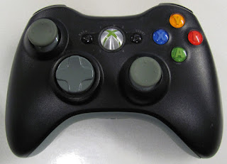
And no. Still no continuity. So I decided I'd replace the whole cable. I had this really awful new Aliexpress Mega Drive controller laying around. I bought couple of these to see if I could harvest the conductive pads from those for the real controllers. Unfortunately they are not even remotely compatible. But they do have the correct cable with all the pins connected. The cable is quite short but that can be fixed with extension cable if needed. Here are some pictures of the controller.
 |
| New cheap Mega Drive controller from Aliexpress |
 |
| Conductive pads not compatible with original Mega Drive controllers |
 |
| PCB is quite nice. Too bad the rest of the construction is really bad. |
 |
| Jackpot. Atari style cable with all the pins connected. |
I wanted the new cable to be detachable so if the Saitek stick would need servicing again it would be easy to separate the front and back halves. So I decided to use 2x5 DuPont connector blocks. I traced which color in the new cable corresponds to which pin and wired the DuPont accordingly.
 |
| Harvested cable with DuPont connector |
After doing the wiring outside the back plate I realized that I'd might have made a mistake. Luckily the hole in the back plate was just large enough to squeeze the DuPont connector through. And the strain relief held the new cable in place perfectly.
 |
| Tight fit |
 |
| Perfect fit |
Now it was just the matter of wiring female DuPont connector to the wires coming from the main PCB. The wire colors of course don't match but I had noted down which wire connects to which pin previously when doing the continuity tests. So just carefully following that it was easy to wire up the DuPont block.
 |
| The other side wired up |
Then the moment of truth. Connecting the DuPont blocks together and testing.
 |
| All connected |
And success. All the buttons and directions were now working properly and this arcade stick got new lease of life it deserved. Then it was just a matter of reassembling everything.
 |
| Everything working and buttoned up |


Comments
Post a Comment